What pressure should be in the hydroaccumulator?
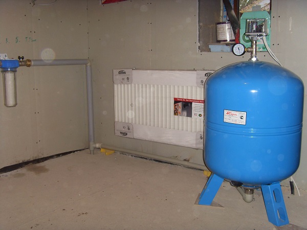
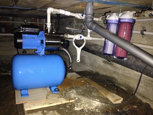
A device such as a hydroaccumulator is necessary to maintain pressure in a pressure water supply system. Often it operates in an ensemble with a pressure switch. Thanks to this operation, it is possible to create a station based on a submersible or surface pump. It is necessary to understand in detail the important question: what should be the pressure in the hydraulic accumulator.
Role in the water supply system
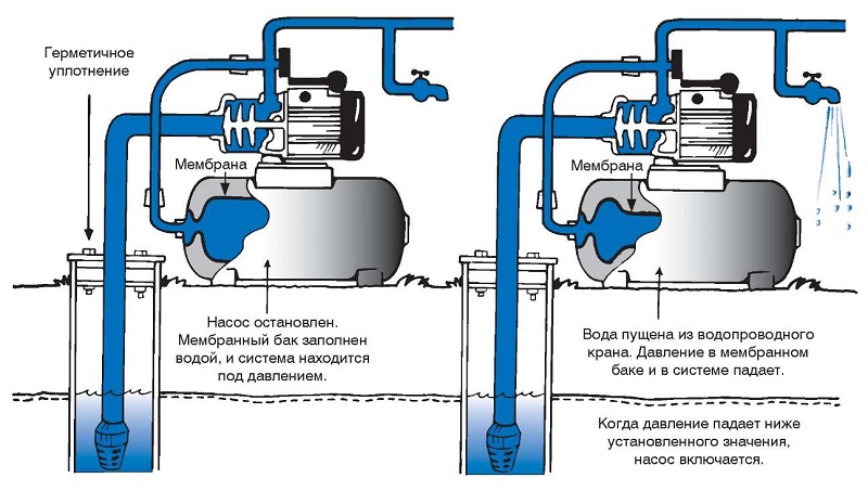
Before dwelling on the pressure parameters in the accumulator, it is necessary to consider its main role in the water supply system. The first purpose of this object is to support and also gradually change the level of pressure of the fluid present in the system.
In addition, the hydraulic accumulator also performs such important functions as:
- provides reliable protection against water hammer (in this embodiment, a change in the pressure of the fluid, which was caused by a very rapid change in its velocity);
- responsible for the minimum water reserve;
- limits the intermittent start of the pump.
From the lighting of the listed functions, it can be concluded that the hydraulic accumulator makes it possible to use a pressure switch, as well as to automate the process of fluid supply. If a hydroaccumulator is not present in the system, the relay will not be able to function correctly, since a rapid change in pressure in the system will provoke its frequent operation.
Such processes will eventually lead to the fact that the water supply will be unstable, and the electric motor may overheat or break, as well as the relay.
Diversity
There are several varieties of hydraulic tanks.
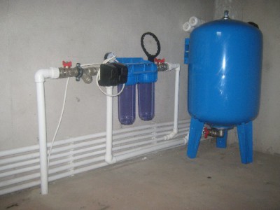
- Responsible for cold water supply. The tank is needed for the accumulation and supply of unheated water. And also it is designed to protect household appliances from dangerous water hammer against the background of a sharp change in pressure in the system. If the pump is activated and deactivated less often, the hydraulic tank will last longer.
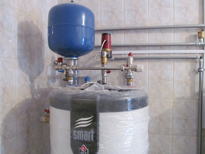
- Providing hot water. Such a device works seamlessly in high temperature conditions.
- Heating. Such instances are called expansive. They operate in the construction of closed heating systems.
Device and principle of operation
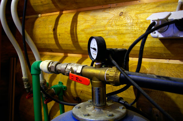
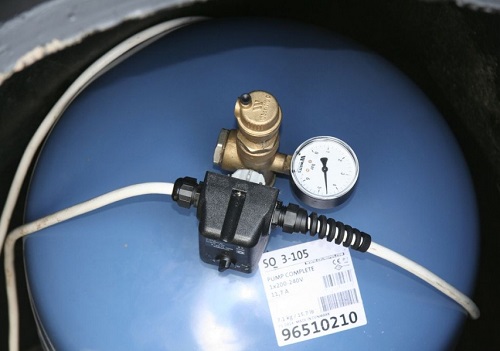
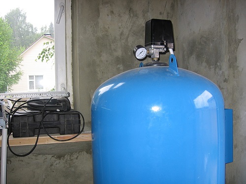
A hydraulic accumulator looks like a small box, represented by different forms with additional elements responsible for control - these parts are located under the lid. The battery is attached to a specific outlet fitting (or tee) capacity. Its mechanism is equipped with springs - they are responsible for adjusting and turning the nuts.
It is worth a closer look at the principle of the hydraulic accumulator.
- The springs in this part are connected to the membrane, which responds to the pressing force. An increase in parameters leads to a contraction of the helix, and a decrease to compression.
- A group of contacts, called to respond to the mentioned processes, closing or opening the contacts, signals this pump. The connection scheme in all cases provides for the connection of its electrical cable to the unit.
- As the drive fills, pressure increases. The spring gives the power of the head, the equipment is activated in accordance with the set values - deactivates the pump, giving it the appropriate command.
- The pressure weakens as the fluid is consumed. The moment the system fixes it, the engine starts up.
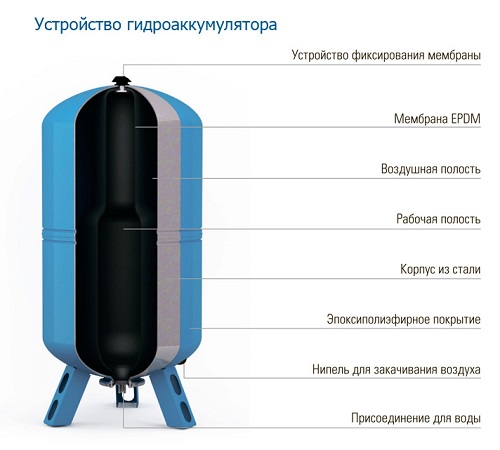
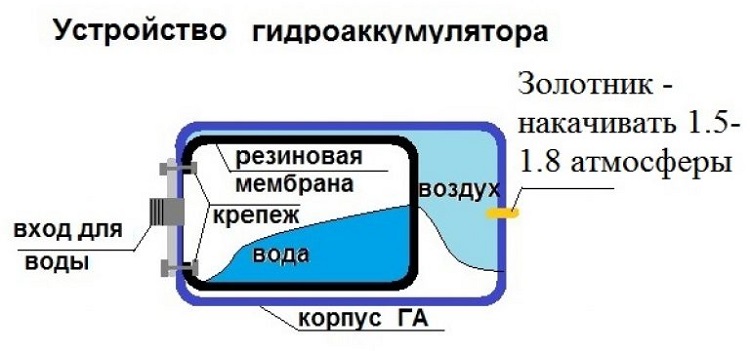
Hydraulic accumulator includes several main components.
- the body is usually divided by a membrane into two separate chambers: one of them is diverted under water, and the second for air;
- membrane - there is water in this part of the tank; membranes made of such material as butyl are generally used; they are not afraid of biological substances, in addition, they are absolutely safe to use;
- nipple - through it air is pumped into the cavity of the tank;
- pneumatic air discharge valve is used to change air pressure; in tanks with a small volume, a tee or tap is used instead of a valve;
- fitting acting as a membrane fixer;
- other constructive elements.
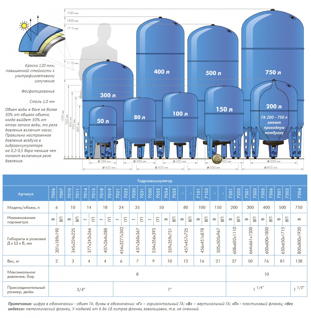
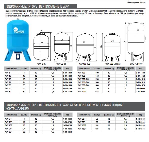
According to experts, the device of the hydraulic accumulator should be as simple and straightforward as possible. Compliance with this requirement is due to the fact that at the time of disassembly from the membrane did not have to completely drain all the water. To avoid collisions with hydraulic losses, you need to select the diameter of the pipeline and the discharge pipe with maximum accuracy. Modern hydroaccumulators are produced with a volume of 2, 5, 24, 50, 80, 100, 150, 200, 300 liters.

Payment
As you can see, the hydroaccumulator in the system solves many problems. The calculation of each parameter is performed by various methods. To determine the amount of fluid that is acceptable to take from the battery when the pump stops pumping fluid from the system, it is recommended to rely on the appropriate table. The water supply will depend on the set pressure switch readings.
What is more impressive is the difference in pressure at start-up and deactivation of the pump,all the more impressive will be the supply of fluid in the hydraulic tank.
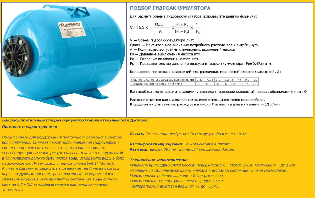
To calculate the volume of the device, you should apply the following formula:
Vt = K x Amax x ((Pmax + 1) x (Pmin +1)) / (Pmax - Pmin) x (Fast. + 1), where:
- Amax is the largest fluid flow in a minute (in liters);
- K is a coefficient that is directly related to the pump engine itself;
- Pmax is the pressure at the time the pump is deactivated;
- Pmin is the pressure when the pump is activated;
- Rozd. - This is the air pressure in the tank.
Optimum performance
In addition to the tank, the relevant indicator of pressure in an empty hydraulic tank is equally important. This value is usually applied to the body of each individual model. It will not be difficult to calculate which parameter will be ideal in this or that case. It is detected, based on hydrostatic pressure, because it depends on the height to which it is necessary to raise the liquid. For example, if the height of the pipes in the dwelling reaches 10 m, then the pressure parameter will be 1 bar. In addition, it is very important to consider that the working pressure of the hydraulic tank should not be more than the starting pressure of the pump.
The smallest difference in this case is 0.5 bar, the largest value is 2 bar (on average).
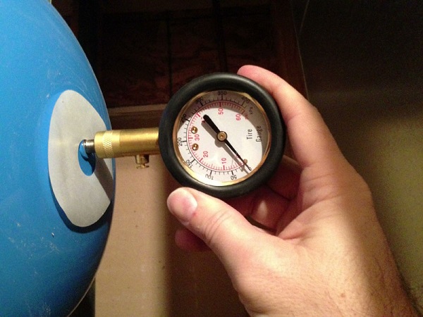
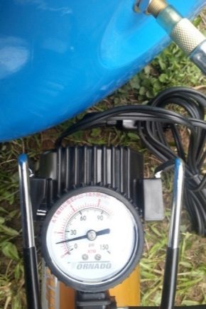
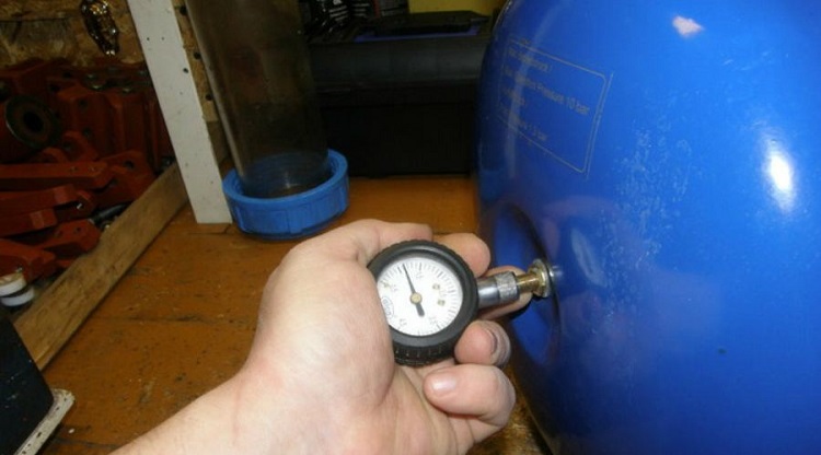
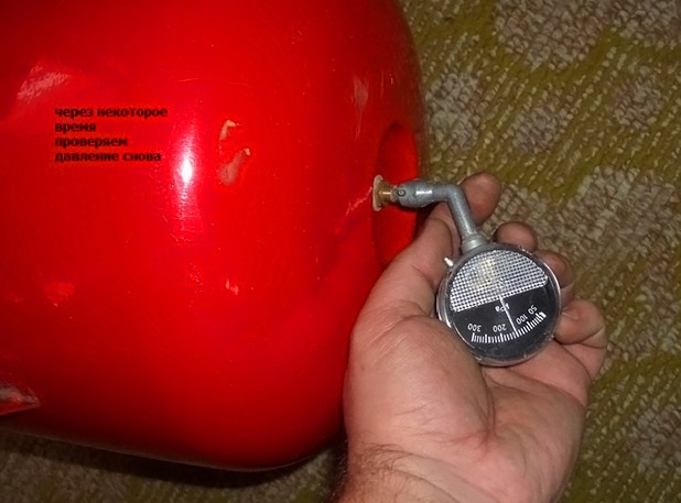
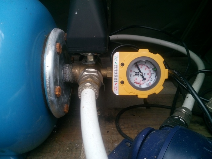
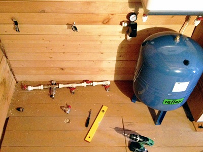
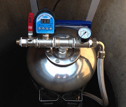
For example, to ensure a stable fluid supply in a home with two floors, you will need a high-quality hydraulic tank having a working power level of 1.5 bar and a top power of up to 4.5 bar. In most cases, manufacturers form air pressure in the accumulator, which is 1.5 bar. However, in certain cases, the values may be different. That is why, before starting to use the unit, it is necessary to check these values using a pressure gauge. This part is connected to the hydraulic accumulator nipple.
As a rule, hydroaccumulators have a pressure indicator of about 10 bar.
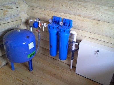
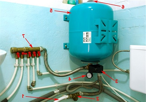
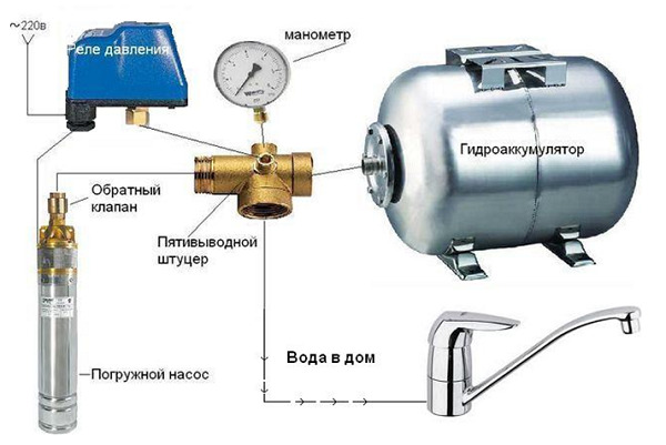
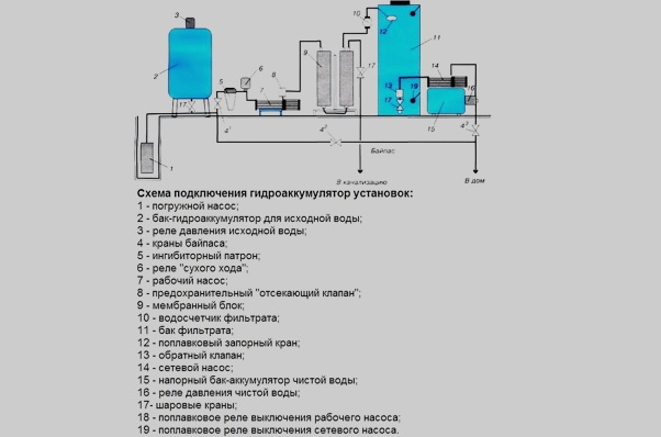
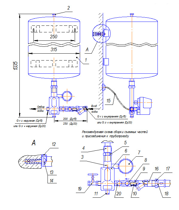
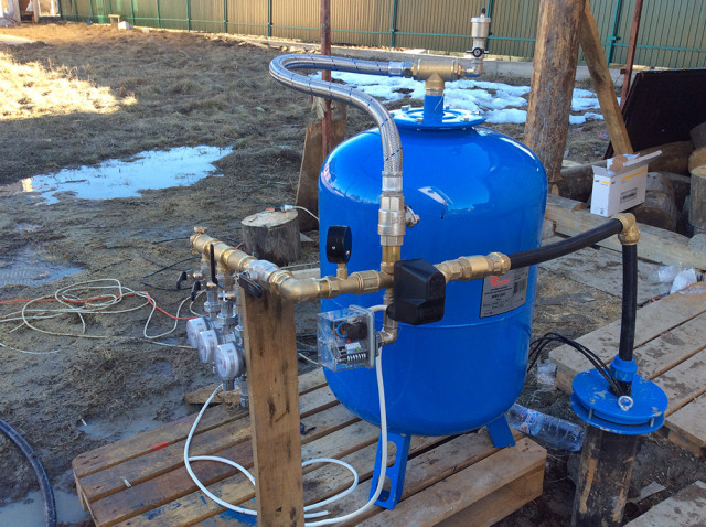
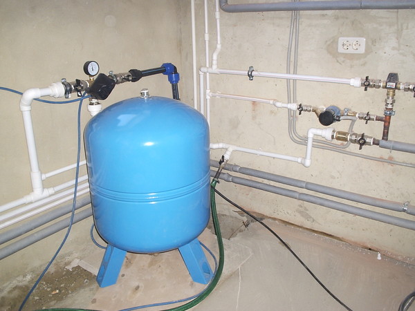
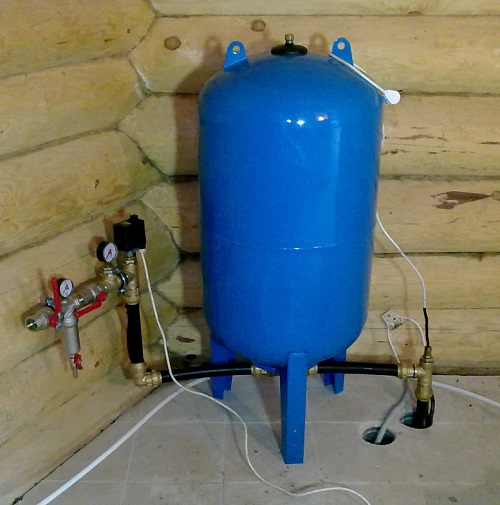
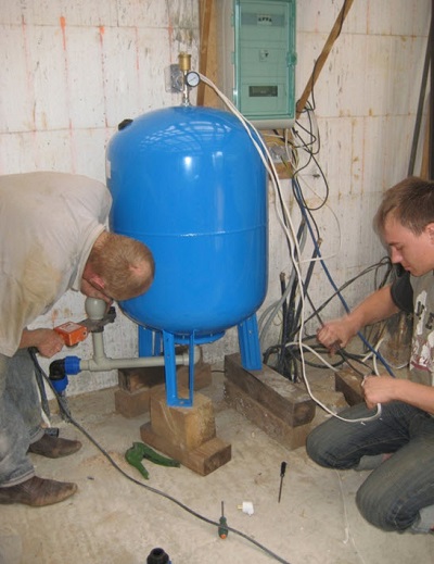
Hydraulic tank connection
The hydraulic tank is the second name of the hydroaccumulator. It can connect to the water supply system in various ways. The choice of a suitable connection scheme mainly depends on the quality of the device used and what tasks it will perform. It is worth considering a few of the most popular ways to connect.
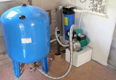
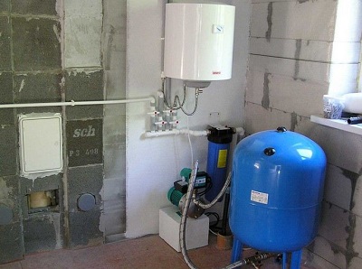
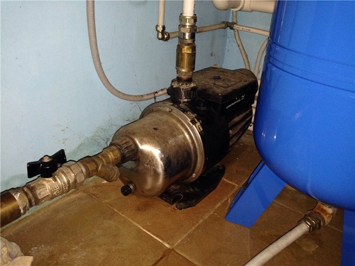
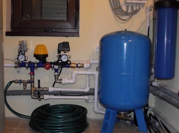
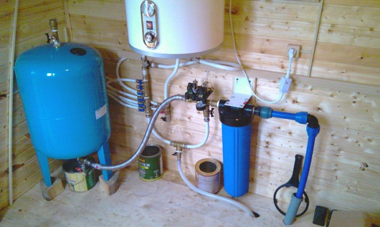
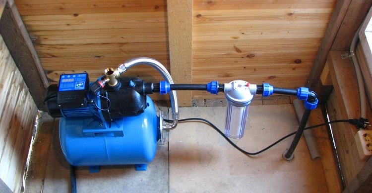
Using surface pump
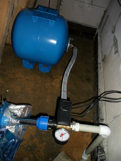
It is worth analyzing step by step how the hydraulic accumulator is connected to the system, if there is a superficial subtype of the pump.
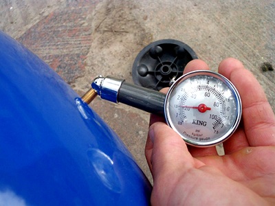
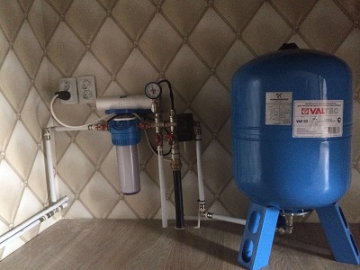
- First you need to check the air pressure in the inside of the tank. It should be 0.2–1 bar less than the parameter on the relay.
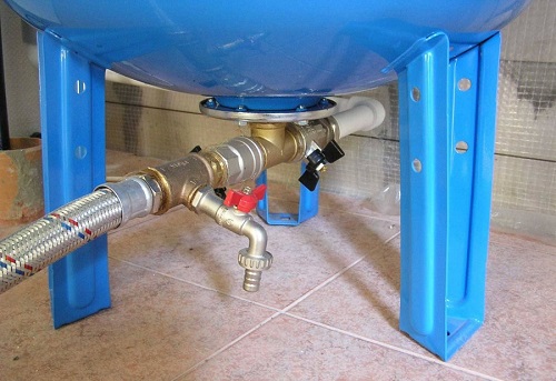
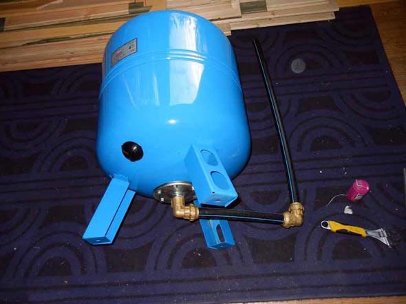
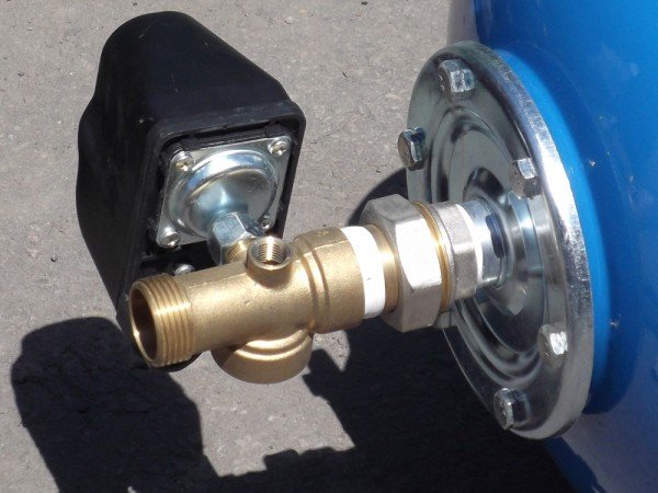
- Then you should prepare the equipment for the connection. In this situation, the technique implies: fitting, pressure gauge, tow with a sealing compound, a relay responsible for pressure.
- It is necessary to connect the fitting to the tank. The connection area may be a hose or a flange with a check valve.
- Then it is necessary to screw other devices in turn.
To deal with the absence of leaks, you need to run the equipment in a test order. When connecting a switch that is responsible for regulating pressure, it is important to inspect all tags. Under the cover are the contact connections - "network" and "pump". It should not be confused wires. If there are no marks under the cover of the relay, then it is better to apply for connection to a professional in order to prevent a serious error.
During the connection, it is very important to keep tightly in check the connections with the threads.
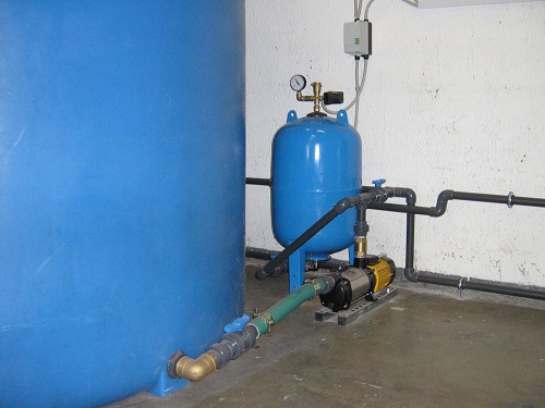
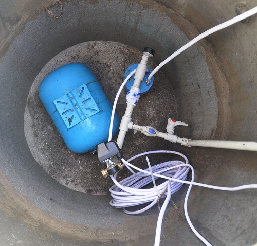
With submersible pump
The submersible or deep type of pump has differences from the above option in thatwhat is located in the conditions of a well or dug well, in other words, in the zone from which water is sent to the dwelling, and in the above situation to the hydraulic accumulator. One detail is very important here - it is a check valve. This element is designed to protect the system from the penetration of fluid back into the well or well. This valve is fixed to the pump near the pipe. For this purpose, threads are cut into its cover.
The first thing is to fix the check valve type, and then connect the hydraulic accumulator to the system.
The scheme is as follows:
- in order to measure out the parameter of the length of the pipe going from the pump of the deeper type to the extreme point of the well, the string with a weight is mainly taken;
- the load is lowered on the bottom, and on the string they make a mark of the edge of the well at the top;
- after removing the rope, you can calculate the parameter of the length of the pipe from the lower plane to the top;
- you must subtract the length of the well, as well as the distance from the section of the transition pipe in the soil to the highest mark of the well;
- In addition, it is very important to take into account the direct location of the pump (pump) - it should be located 20-30 cm from the bottom.
Relay Setup
Connected appliances are still not ready for launch. To this end, it should conduct a competent setting. This process is covered in the fact that certain parameters of starting pressure and deactivation are selected for the relay.
Scheme and numbers
The above values are set as follows:
- activation when the pressure drops to 1.4–1.8 bar;
- deactivation with increasing pressure by more than 2.5–3 bar.
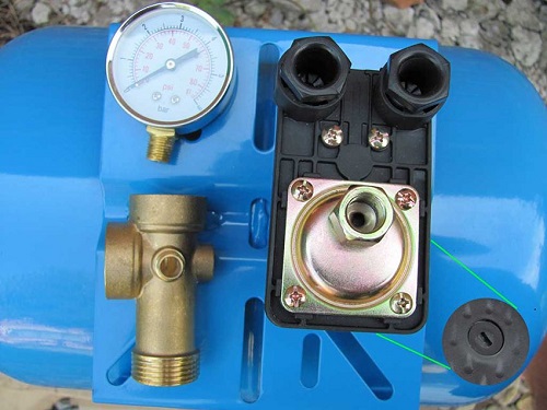
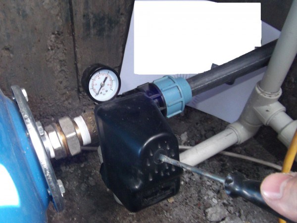
To establish the necessary indicators, it is important to determine the correct values in the system as accurately as possible. Identification of these marks should be made at the stage of calculating a set of water supply systems and up to the moment when specific equipment will be selected. Relay settings should be made in an open housing, so it must first be removed. Adjustment is carried out by adjusting the tension of the spring elements.
To make it more convenient, the springs are marked with the following letter symbols, which are indicated on the body:
- P is a spring responsible for adjusting the level of P startup values, it has large dimensions;
- Δ P is the spring required to change the difference between the upper and lower levels of R.
The scheme of setting the settings is simple: the adjustment is made by turning the nut, which is responsible for the level of compression, for this reason it is better to take the key. The process of compression of the springs will be made by turning clockwise. So, it is possible to ensure the increase in the strength of its impact. If you want to reduce the power of the actuation pressure, you must also carefully turn the nut in the opposite direction, which will lead to a loss of elasticity of the spring part, as well as a decrease in its impact. So, a minor value for trigger pressure parameters will be set.
Basics and rules of adjustment
It is necessary to learn more about the basics and rules of regulation of the relay.
- First you need to turn on the crane. After that, the system will start and the fluid intake will begin. At this time it will be noticeable that the P-value becomes lower. This will last until the pressure reaches the lowest set value. In the future, the relay will work, the contacts will close, and the pump will turn off. It is worth looking at the pressure gauge - remember or write down the pressure parameter during the pump start.
- Now you need to close the tap. The liquid supply will stop, but the pump will continue to function at this time. This will entail an increase in pressure in the system. When it reaches the largest mark fixed for the system, the turn of the relay will come. At that moment the contacts will connect, and the power will stop flowing to the pump, which will cause it to turn off. And again you will need to look at the pressure gauge - write down its parameters at this minute.
- In the future, you will need to compare the pressure parameters that were noted in the minutes of switching on and off the system, and the values set at the factory (they are usually indicated in the documentation that comes with the device).
- If it is noticed that the values of the P-inclusion are not the same, then you should take a wrench. They need to turn the nut to tighten or loosen the large spring. So, if the indicator needs to be done more, then the spring needs to be tightened, and if reduced, then loosen. You should always act as carefully as possible.
Do not rotate the elements more than one turn.
- The listed actions must be repeated until the required pressure parameter is reached.
- If it is noticed that the fixed indicator of pressure off does not correspond to the required one, then it is necessary to turn a small spring. The nut should be tightened to make the value larger or weaker if you want to lower it.
- You must repeat the above steps to achieve the value that you want to put.
When calculating the water supply system, it is important to take into account not only the water pressure indicators, but also the same parameters relating to air - they are always present both in the hydraulic units and in the pipes. Air pressure can be measured up to the moment the water enters the station. This can be done by turning to a conventional automobile pump equipped with a pressure gauge, which is used to pump the wheels. It should be borne in mind that the air pressure must be maintained at a constant rate, which will favorably affect the performance and durability of the equipment.
To ensure stable operation, it is necessary to make a measurement once every three months, and also to maintain the required parameters at an appropriate level.
Of course, it is permissible to apply a simpler adjustment option, which includes the following rules:
- after adjusting the pressure switch for the hydraulic tank, setting the values of the largest and smallest limits, it is necessary to turn on the water supply;
- in the course of use, it will be necessary to periodically take readings of the pressure gauge in minutes of launch, as well as stopping the operation of the equipment;
- if the values change, it will mean that the air pressure in the tank has also changed, so pumping with a pump will be needed.
The control of air pressure in tanks is as important as the control of water pressure. There is no point in doing the detuning of the upper pressure parameter on the relay when the entire pumping station is filled with liquid — in this situation, the total air and fluid pressure will be recorded. In the future, when self-tuning the relay, it is possible that it will encounter certain difficulties, because the readings will not be entirely correct, which is why the entire system will not act clearly. It should be borne in mind that all settings should be determined as clearly as possible, given that all the components of the equipment have a strength margin. Exceeding these values can cause severe system damage.water supply.
In addition, it is very important to take into account some nuances when adjusting the pressure switch for the hydraulic tank. When an oversized indicator is set, the pump power parameters may not be enough. The lower the lower value is set, the more water can be pumped until the water supply is turned off.
For this reason, the smallest values for pump deactivation should be no more than 0.8–0.9 atmospheres.
Preparation and example
It is worthwhile to dwell on the immediate preparation and on the example of the exhibited required parameters.
The technique is prepared as follows:
- you must first connect the tank;
- then you should adjust the control unit under pressure (at this point, the automation does not deactivate the system);
- in the internal space of the equipment, the pressure drops and may be less by 10–13% than at the station itself (more precisely, by 0.6–0.9 atmospheres less than the mark at which the motor starts);
- then all the taps need to close;
- the set parameter should be checked with a pressure gauge over an hour to note that there are no leaks;
- then the cover of the housing part of the unit is removed to open the way to the nuts and springs.
It is worth considering a specific example of how to set up a relay with a setting of 3.2 atm for deactivation and 1.9 atm for starting in a two-story home.
- It is necessary to start the pump to determine the pressure in the system. It should cover the cumulative half of the unit, as well as make the pressure higher.
- It is necessary to determine at what value of the manometer the technician will turn off (as a rule, it is 2 atm). In the case of overstatement, a small spring begins to act, which will be clearly noticeable.
- If the motor stops at a value of 3.2–3.3 atm, then this indicator is made smaller by rotating the nut on the small spring by a quarter of a turn, since it is very sensitive. This should be done until the motor is turned off.
- Next, you should do the verification with the help of a manometer: 3–3.2 atm will be enough.
- Then the crane is started to reduce the onslaught and to release the hydraulic tank from the liquid. It is necessary to fix the pump start-up value with a manometer (usually, this is 2.5 atm). At this value, the minimum pressure will be obtained.
- To reduce the lower threshold, you need to turn the bolt of the large spring in the counterclockwise direction. After that, the pump starts up to increase the pressure to the desired level. Then you should measure the pressure gauge. The optimal parameter in this situation is 1.8–1.9 atm. With a “failure” the nut must be turned clockwise.
- In conclusion, you need to slightly adjust the fine spring, making the thresholds more accurate.
Faults
Most often, accumulators fail due to the following reasons:
- too frequent start / stop of the pump;
- valve leakage;
- Inlet / outlet water flow too low.
Before identifying the cause of the weakening of pressure, it is necessary to determine what the exact pressure should be in the station’s hydraulic tank.
In this case, the problems may be as follows:
- wrong pressure;
- damage or deformation of the membrane part or housing;
- breakdown of the relay.
Deal with the difficulties encountered in such ways as:
- pressure build-up in case of its decline;
- restoration of the damaged membrane;
- restoration of damaged housing;
- adjustment of the differential, based on the mode of the pump.
Prevention and maintenance
To hydroaccumulator served longer, it should be treated accordingly. Technique will require timely maintenance, as well as periodic preventive measures.
The preventive and repair measures include the following:
- periodic inspection and adjustment of mechanical elements, characterized by strong sensitivity;
- cleaning contacts;
- if the unit does not work, do not rush and disassemble the mechanism, for a start it is worth tapping the case slightly with a light object;
- hinges "rocker" need to handle a special lubricant about 1 time per year;
- No need to tighten the adjusting nuts until it stops - because of this, the mechanism may stop its work.
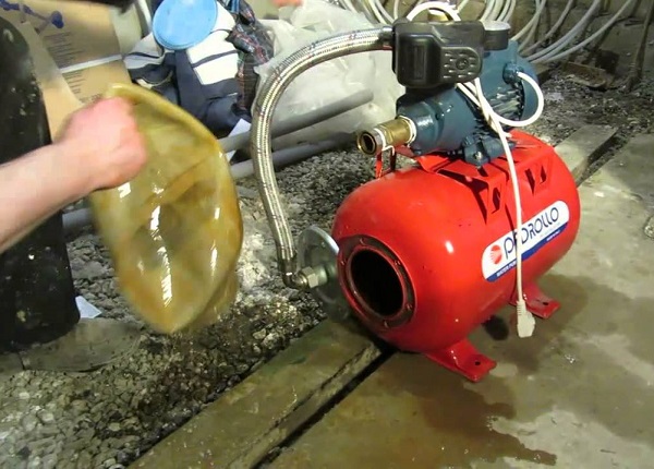
In the event that there is a sharp drop in pressure, it malfunctions or does not function at all, you should not hurry to draw any conclusions, you do not need to throw out the device. Garbage in place of the membrane often does not allow the unit to function correctly.
To get rid of this problem, you need to do the following:
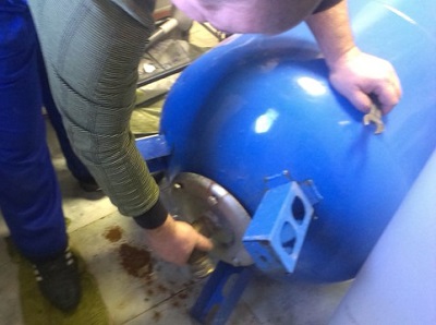
- you need to unscrew the four bolts on the bottom;
- then it is necessary to remove the cover with the pipe and the cover;
- Carefully wash the membrane, observing maximum caution; need to wash and the cavity that surrounds it;
- now it is necessary to fix all the components in the reverse order;
- again fix the thresholds and make a test run.
Professionals advise, before setting up the relay correctly, not to allow the upper threshold to be exceeded by more than 80% of the maximum permitted values for a particular unit. Usually this information is indicated in the instructions for the technique. In order for the equipment to work well and properly, air must not be present in the water supply system. Sometimes (about once every 3–6 months), it is necessary to check the set response thresholds, as well as the values of pressure in the accumulator. It should bleed and pumped air.
Before setting the necessary parameters, it is necessary to know whether the pressure switch and the device can transfer the necessary loads.
For how to replace the accumulator membrane with your own hands, see the video below.


